Everyone knows what an antenna is when they see one and many people generally understand its purpose. But beyond that the science of wireless communication is often left to IT specialists and engineers. It helps to tell yourself circular graphs aren't really that overwhelming. Here are the basics for a more technical understanding of antenna beams and how they work.
Radio Communication Terms
 The foundation of antenna theory is part of radio technology in which antennas can both transmit and receive electronic signals through the air. These signals are mathematically defined by frequency (measured in cycles per second called Hertz or Hz) and wavelengh (λ) measured by distance of each cycle in meters or centimeters. The radiation pattern of an antenna is called beam width.
Both incoming and outgoing radio waves work against resistance, which is measured in Ohms (Ω). Impedance is the amount of resistance that occurs when voltage is applied. High impedance in a device means limited electric current is flowing through, whereas low impedance means current is flowing freely with little resistance.
As an antenna is a tool for two-way communication, it adheres to the "property of reciprocity," in which certain wave patterns are the same for both modes of communication. Directional patterns, directivity, effective lengths and antenna impedances are equal for sending and receiving signals.
Since radio signals are distributed from an antenna in all directions, the graphs used to measure coverage areas are circular. But perfect circles don't usually occur in nature, especially when it comes to something as volatile as radio waves. So the waves coming from antennas take on angles based on numerous environmental and technological factors. It's important to measure radio coverage to control a signal better so that it's not causing interference with other radio operators.
Importance of Antenna Beams
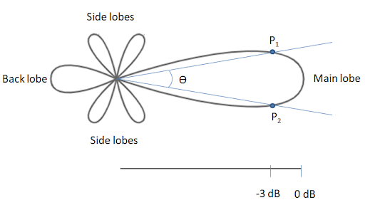
An antenna beam can be represented on a circular graph as a "lobe," which is a round pattern with flat parts. The diameter (D) of this lobe is used in equations for measuring beam presence and strength. Most of the radiated power of a signal is represented by beam width. Radio signals generate a major lobe connected with smaller minor lobes. Dividing the major lobe into two halves helps analyze the symmetry of the wave pattern.

A standard value when measuring beams is "Half Power Beam Width" (HPBW), which reflects half the power of the signal's peak intensity (P1 and P2 in the figure above). This metric, measured by angular degrees or radians, is used for comparing relative power to peak power in the antenna's field. This beam width data tells a technician how much signal strength exists in a given direction as well as the antenna's radiation distance. This value fluctuates according to signal behavior. Higher frequencies are more directional and have narrower beam width while lower frequencies produce the inverse effect.
Another important metric is First Null Beam Width (FNBW), which measures angular separation from the main beam. It represents the angle between two tangents on both sides of the wave pattern in relation to the radiation's point of origin. While HPBW helps determine the antenna's signal resolution capability, FNBW is useful for analyzing how antennas interfere with each other. Half power beam width can be expressed with this mathematical equation:
HPBW = 70λ / D (70 times wavelength divided by lobe diameter)

Beam width, which is often expressed as "beamwidth" in engineering, can vary based on multiple factors including antenna type, design and frequency. Analyzing this width helps technical experts determine how an RF signal will affect a device.
The measurement is used for testing equipment and calculating signal strength in a specific direction. Tests must be repeated to verify accuracy of measurements.
Any given antenna has limitations based on frequency, bandwidth, polarization and other factors, so it's important to consider an appropriate antenna for a specific application. Beam width is one of the most important factors for selecting the right antenna. Some applications require a more directional coverage path while others may need more circular coverage.
Conclusion
Understanding beam width is a key to measuring radio coverage for an area. This information is useful to technicians for optimizing radio signal strength and coverage areas. While circular 2D graphs showcasing 3D data can be confusing, the important point to remember is the size and shape of the signal represented by a lobe in relation to the center point. Ultimately, this information helps decision makers select the right antenna and its placement for their applications.
ATC Academies can use SkyRadar's NextGen 8 GHz Pulse radar and FreeScopes Basic I to measure antenna beams.


