This document describes exercises for the SkyRadar 24 GHz FMCW Radar.
4. Relationship Bandwidth and Resolution
1 Range Resolution
1.1 Abstract
Demonstrating the relationship between modulation and range resolution. Caused by the fixed number of range cells increasing the dimension of the resolution cell increases as well the unambiguous range. But the transmitted power is limited – the real maximum range depends on the conditions of the fundamental radar equation. Thus there are two independent limitations in radar: the pulse period and the energetic conditions.
1.2 Performance Indicators
- Learners will be able to understand and interpret the relation modulation and range resolution.
- Learners will be able to identify the most suitable range calibration to receive the best image.
- Learners will be able to understand and interpret the results indicated in the different scopes.
1.3 System Set up
The radar should be placed on a desk, in a free view at targets in 3-10 m distance.
If available use the mobile target positioning system.
The lecturer will start up the FMCW radar.
1.4 Experimental Procedure
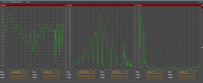
Arrange freescopes: place 2 A-Scopes, and the controls to the canvas.
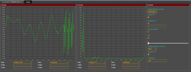
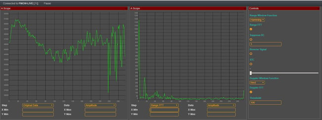
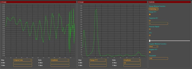
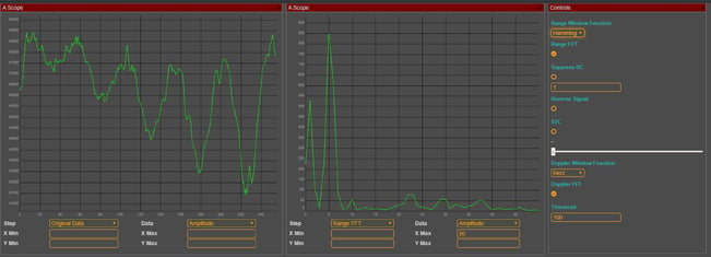
Ideally set the left A-Scope to raw data, and the 2nd to Range FFT. Ideally set the window function in the controls to Hamming. Thus we will remove the windowing effect.
Do the following steps:
- Look at raw data and see the effect of changing range, when moving the target away from the radar.
- You might want to take screenshots at several positions and save them in a document.
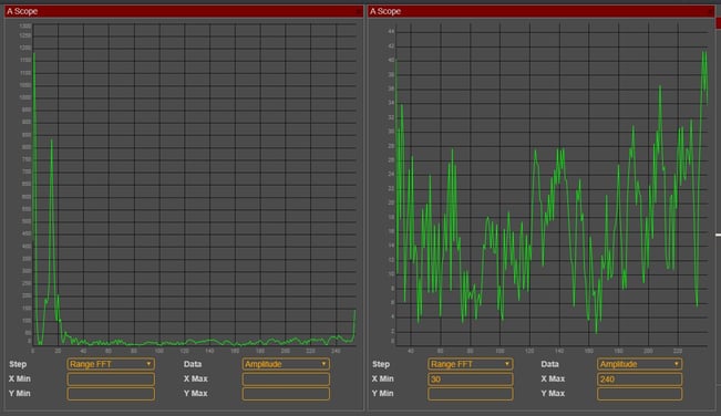
- You will see a change in frequency in the raw data (left A-Scope). In the range FFT, we see the that the peak of the object moves to the right and the amplitude gets weaker.
- you can zoom into various sections of the graph by marking it with your mouse.
2. Range and Speed
2.1 Abstract
We calculate the range by one chirp. With 256 chirps we can calculate the speed.
2.2 Performance Indicators
- Learns will be able to conduct a measurement with frequency modulated signals and calibrate the scopes to achieve a reasonably good measurement result.
- Learners will be able to see the different steps in the signal conversion including the measurement of range and speed
- Learners will be able to understand and interpret the results indicated in the different scopes
2.3 System Set up
The radar should be placed on a desk or tripod, 3-10 m distance.
After FreeScopes has been started, please open 2 A-scopes and the controls panel.
2.4 Experimental Procedure
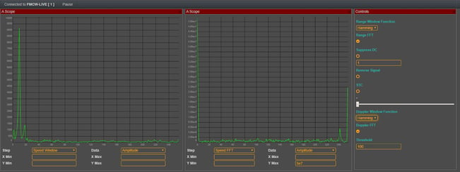
Set the left A-Scope to speed window, and the right A-Scope to speed FFT.
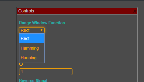
Set range window function and doppler window function to Hamming.
The radar is recognizing distances and the speed. Move with a reflectors (e.g., metallic target) in front of the radar.
3. Threshold Filter
3.1 Abstract
The threshold filter is to determine the power threshold above which any return can be considered to probably originate from a target.
3.2 Performance Indicators
- Learners will be able to recall and describe the goals and working principle of the threshold filter function.
- Learners will be able to apply threshold filter function, configure and fine-tune the settings to get a clean signal of the target.
- Learners will be able to adapt settings on different targets
- Learners will be able to understand and interpret the results indicated in the different scopes
3.3 System Set up
The radar should be placed on the rotary tripod. Several targets (in a sequence or simultaneously) will be placed on a mobile target positioning system.
3.4 Experimental Procedure
First optimize the threshold function on a static target. Place a target in around 5 meters in front of the radar.
- In a first step try to optimize with the A-Scope. Determine the target along the x-axis. Now reduce the impact of noise while increasing the threshold until you find the right optimum between suppression of noise and visibility of the target.
- Now let us do the same exercises in the PPI scope. First move the target to a different position. Then start the motor of the radar, so that the radar rotates.
Now try to optimize the PPI Image with the threshold - Let us move forward to a more realistic setting. There are several targets, some of them might be further away. Try to find a compromise when setting the threshold where closer and more far away targets are seen
- Repeat this exercise with moving targets.
4. Sensitivity Time Control
4.1 Abstract
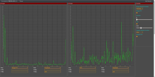
Sensitivity time control (STC) is used to attenuate the very strong signals returned from nearby ground clutter targets in the first few range gates of a Radar receiver. It will avoid that same size targets close to the radar source send much stronger signals than those farer away. This function will help to improve the results received in the previous exercise.
4.2 Performance Indicators
- Learners will be able to recall and describe the goals and working principle of the STC function.
- Learners will be able to apply the STC function, configure and fine-tune the settings to get a clean signal of the target.
- Learners will be able to blend the STC function with the threshold function
- Learners will be able to understand and interpret the results indicated in the different scopes
4.3 System Set up
Use the arrangement of the Threshold exercises.
4.4 Experimental Procedure
Repeat the exercises done in the Threshold chapter. But now compensate the attenuation of signals further away from the source. Do it in a way that targets which are closer and targets with are farther away are best seen.
- start in the A-Scope, a static source and a static target
- continue in the PPI, a rotating source and one and then several static targets
- stay in the PPI, rotating source and move one or several targets around.
- try to understand also other targets around (like the walls of the laboratory). Try to choose some more of these architectural targets from our lab and tune the PPI in a way, that also these targets are well seen.
4. Relationship Bandwidth and Resolution
4.1 Abstract
Bandwidth has a direct impact on the range resolution of a radar. These exercises will allow to experiment on this dependency.
4.2 Performance Indicators
- Learns will be able to conduct measurements on frequency modulation and calibrate the scopes to achieve a reasonably good measurement result.
- Learners will be able to describe and explain the impact of changes in bandwidth.
- Learners will be able to measure single reflecting objects in short distances with various bandwidth of frequency modulation.
- Learners will be able to understand and interpret the results indicated in the different scopes
4.3 System Set up
The professor will vary the bandwidth in the radar settings. The students will experiment on the different bandwidth using two A-Scopes and a control panel.
In the left A-Scopes, the student will show raw data. In the 2nd A-Scope, students will show range FFT. The window settings in the control panel shot be set to Hamming. The X-max value should be set to 50.
4.4 Experimental Procedure
The experimental set up shows the results for one specific bandwidth.
The students should start with bandwidth 900 MHz.
Then the professor should go down to 450 MHz.
5. Windows Functions
5.1 Abstract
When we analyze a radar data, it is never the complete data, but only an interval, a subset. The problem, when we cut out the interval from the complete data, the external data subset has an influence on our analyzed data. Windows functions have the task to bring the data outside our window of analysis (interval) close to zero.
5.2 Performance Indicators
- Learns will be able to conduct a measurement with the FMCW radar under application of alternative window functions. They will be able to achieve a better measurement result than without the windows function.
- Learners will be able to describe and explain the effect of windows functions (in conjunction with their theoretical knowledge they should be able to explain the functions they are seeing).
- Learners will be able to understand the different stages in the signal conversion chain and interpret the different stages in the evolution of the signal.
5.3 System Set up
The radar will be placed on the rotary tripod, best looking at targets in 3-10 m distance.
Work should be done on the A-Scope
5.4 Experimental Procedure
Experiment 1: without Window funciton
Load two A-Scopes to into your control center and a control panel.
Do not apply any range window function to the signal (“Rect”)
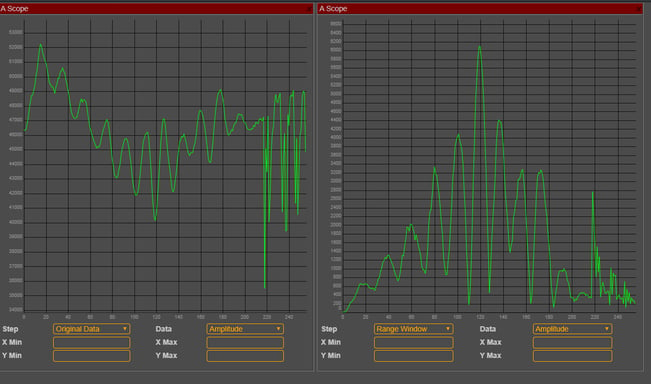
Keep the left A-Scope at original data. Set the right one to range window.
Both A-Scopes should look the same.
You could add a third A-Scope, set it to Range FFT and analyze the range function.
Experiment 2: with Hamming Function
Now apply the Hamming function to the right window. You will see how the signal evolves.
You may use all 3 A-Scopes in a row. Look at the clear Range image after FFT.
Repeat the exercises looking at I and Q signal independently. Work with targets. Try to get a feeling where each of the windows functions has the best performance.
6. Bringing it all together
6.1 Abstract
In the previous exercises, we learnt several “tools” and the underlying technology to create a synergetic toolset, able to create clear images for every situation, in a static and dynamic context. We blend threshold, STC, Windows functions and more. Also we will use additional features in the FreeScopes Software
6.2 Performance Indicators
- Learns will be able to conduct measurements and optimize the results while blending various tools from the given toolset.
- Learners will be able to describe and explain the advantages and disadvantages of each filter, application and scope.
- Learners will be able to work with the I and Q data
- Learners will be able to understand and interpret the results indicated in the different scopes
6.3 System Set up
The radar will be placed on the tripod, best looking at targets in 3-10 m distance.
6.4 Experimental Procedure
- Place the first static target and try to optimize the image, using several of the functions learned above
- Repeat the exercise with several targets, one close to the source, one in the middle, and one further away. Try to optimize the image for all.
- Now operate with moving targets. Experiment also with only the I and only the Q part of the signal.
- Work on the minimum and maxium of the x scale. Cut out the noise of the radar source (at the beginning of the signal) and the end of your laboratory (the reflection of the wall). You will now be able to use the full range of the vertical axis for your signal.


